2. Parts List
1 |
|
1 |
|
12 |
|
4 |
|
4 |
|
1 |
|
2 |
6x6x10mm Tactile Pushbutton |
1 |
|
1 |
|
1 |
CR1220 3V Lithium Cell Battery |
2 |
|
1 |
3. Print the Case
3.1. 3D Print Case
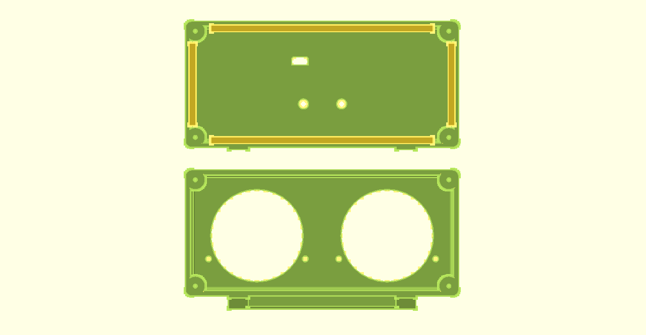
3D Print the front and rear of the case. All parts print without support. I have used both 0.2mm and 0.3mm layer heights with 3 top, bottom and perimeter shells in PLA.
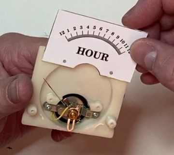
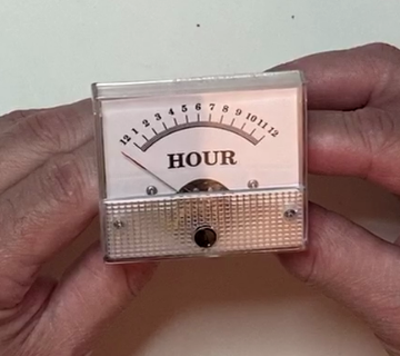
4. Replace Meter Scales
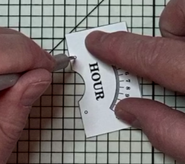
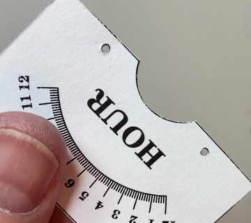
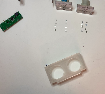
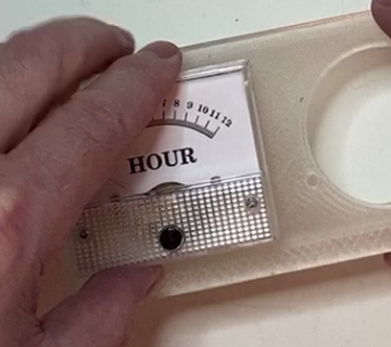
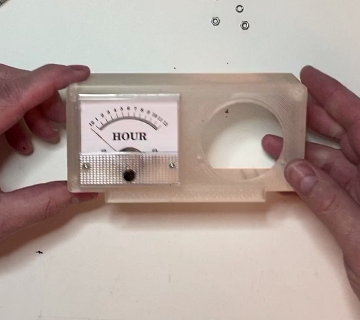
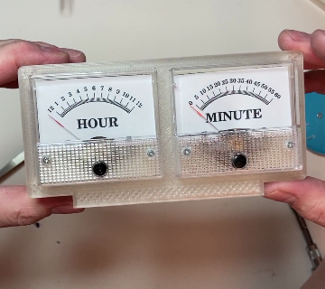
4.1. Print New Meter Scales
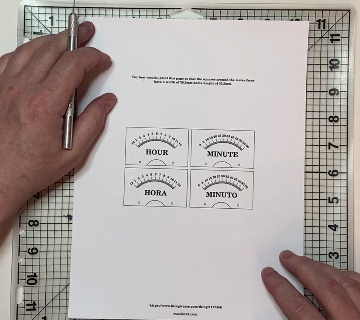
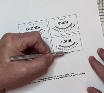
Print the new panel meter scales. The Hour and Minute meter scales were created using Inkscape. The source SVG file is provided in case you wish to make changes, as well as 300 and 600dpi PDF files that can be printed at 100% scale. Print the meter scales so that the squares around them have a width of 59.5mm and a height of 35.5mm.
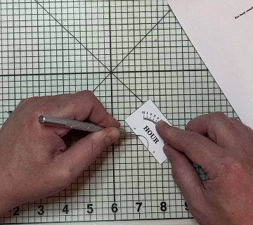
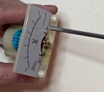
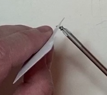
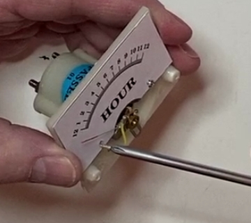
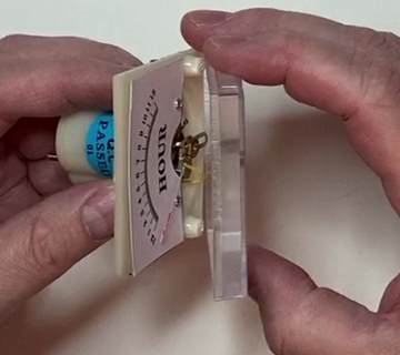
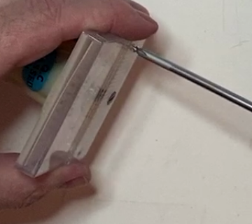
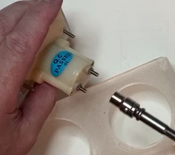
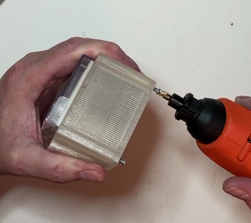
4.5. Use Screw to Enlarge Holes
Use one of the meter screws to enlarge the mounting holes in the new meter scales.
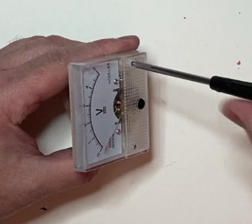
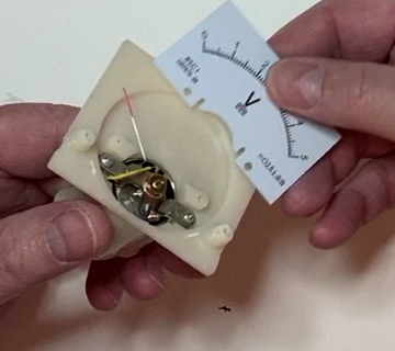
4.7. Replace Screws Holding Scale
Replace both screws holding the new meter scale. If the new meter scale does not lay flat, use a small bit of glue stick on the back of the top corners.
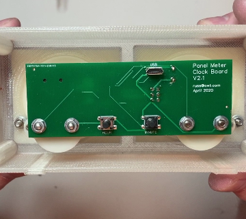
5. Assemble Clock PC Board
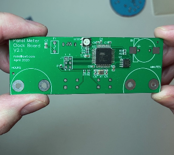
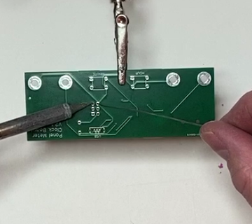
5.1. J1 ICSP Connector
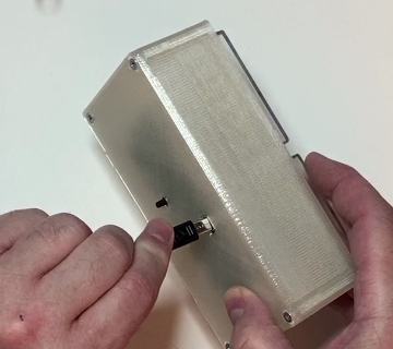
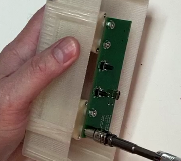
Place and solder the 6 pin ICSP connector in the area labeled J1. Use tape to temporarily hold it in place if needed.
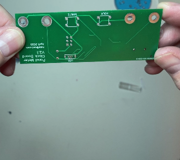
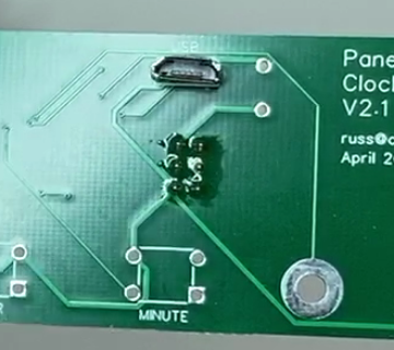
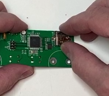
5.2. USB Connector
Place and solder the micro USB connector to the back side of the PC board in the area labeled USB.
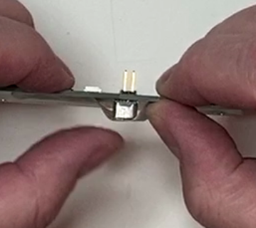
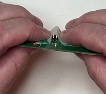
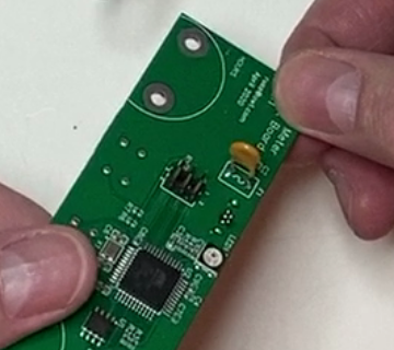
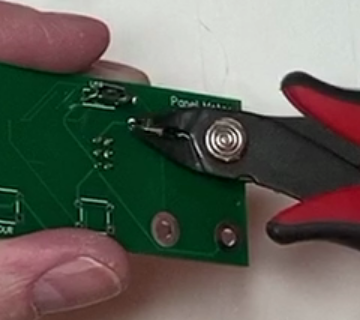
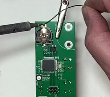
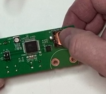
5.3. F1 500ma Polyfuse
Place and solder the 500ma Polyfuse in the area labeled F1 and Trim the excess leads flush with the PC board.
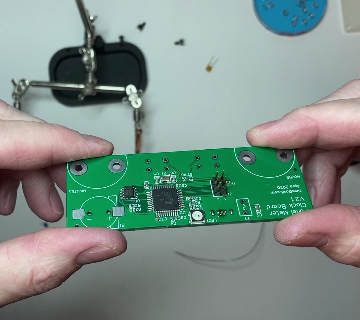
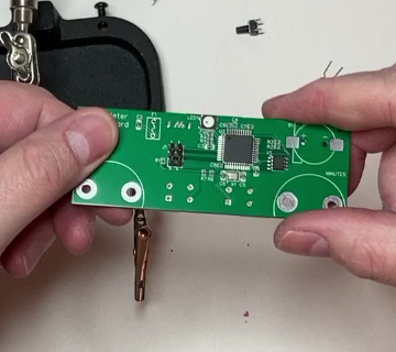
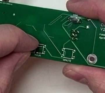
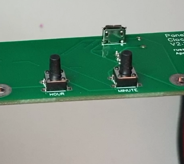
5.4. HOUR and MINUTE Tactile Pushbuttons
Place and solder the time adjust buttons on the back side of the PC board in the areas labeled HOUR and MINUTE.
6. Programming
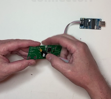
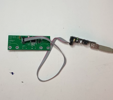
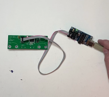
6.1. Connect ICSP Programmer
Connect the ICSP Connector to a ICSP Programmer like a USBTiny or another Arduino as show on the Arduino Website <a https://www.arduino.cc/en/tutorial/arduinoISP
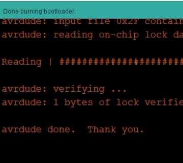
6.3. Disconnect Programmer
Once the bootloader is programmed, disconnect the PC board from the programmer.
6.4. Connect USB Cable
Connect a USB Cable from your computer to the micro USB Connector on the PC board.
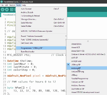
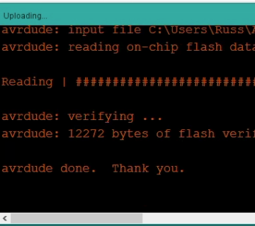
6.5. Upload Clock Program
Use the Arduino IDE to upload the panel_meter_clock2_1 sketch.
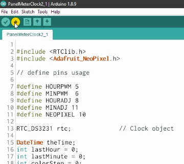
The clock time will be set to the current time of the computer used to upload the sketch.
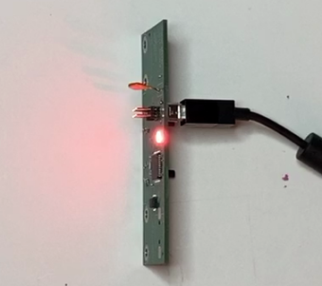
The NeoPixel on the PC board should light and start to change colors. If the NeoPixel does not light up, go back, and check your solder connections for shorts or other issues.
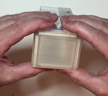
7. Final Assembly
7.1. Install Spacers
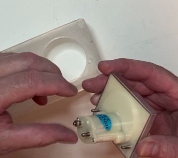
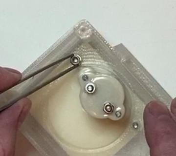
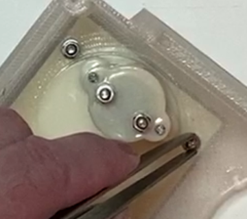
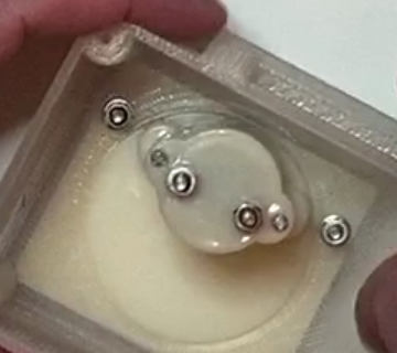
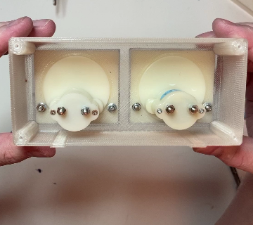
Place a M3 hex nut on both of the meter input screw terminals on the back of each meter. These are used as spacers to set the distance of the PC board to the rear cover of the case.
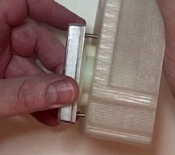
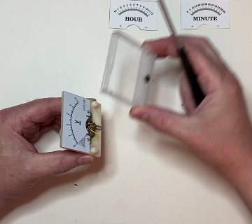
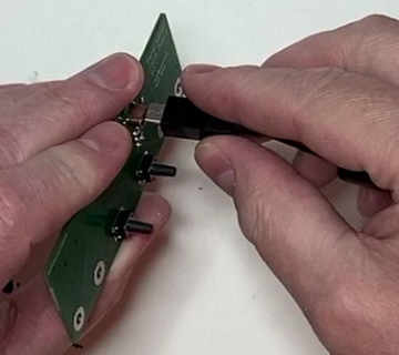
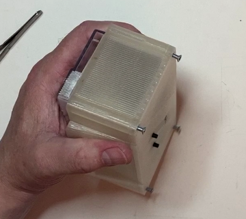
7.3. Secure Hour Meter
Secure the meter in place with a flat washer, a split washer and a M3 hex nut on each of the meter’s mounting studs. Needle nose pliers or Tweezers may be useful here, since there is not much room.
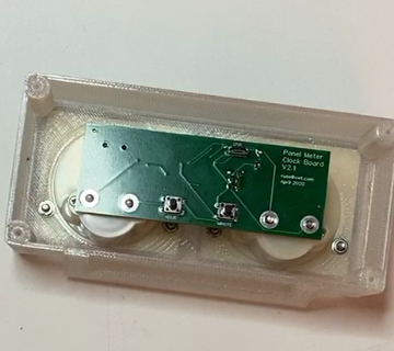
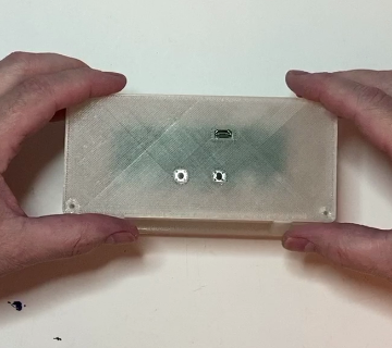
7.5. Secure PC Board
Secure the PC board to the back of the meters with four M3 hex nuts. The micro USB connector and tactile buttons should be facing out to the rear of the case.
7.9. Configure the Clock
To configure the clock connect a USB cable between a computer and the clock.