1. TurtlePlotBot Chassis
1.1. Hardware Parts List
Quantity |
Description |
|---|---|
2 |
3mmx50mm Dowel Pin 304 |
4 |
Sleeve Bearing 3x5x5mm |
1 |
18650 Battery holder |
1 |
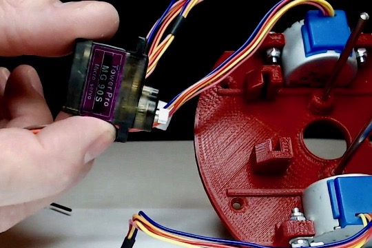
MG90S Servo |
2 |
28BYJ48 Stepper motor |
4 |
M2x5mm self tapping screw |
8 |
M3x10 machine screw |
2 |
M3x5 flat head machine screw |
6 |
M3 hex nut |
6 |
M3 lock nut |
2 |
0.4x10x20mm steel spring |
1 |
1/2” slingshot ammo ball |
1 |
M3x15 (or 12) machine screw |
1.2. 3d Printed Parts
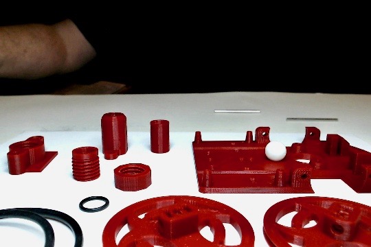
1.2.1. Printing Instructions
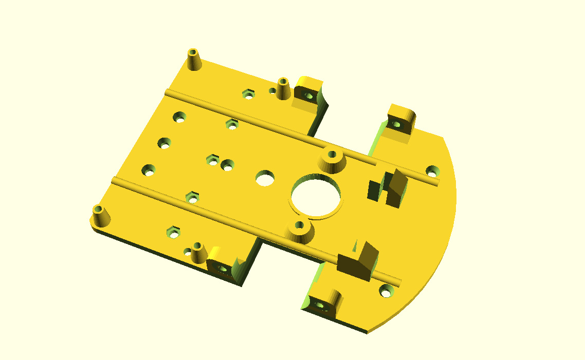
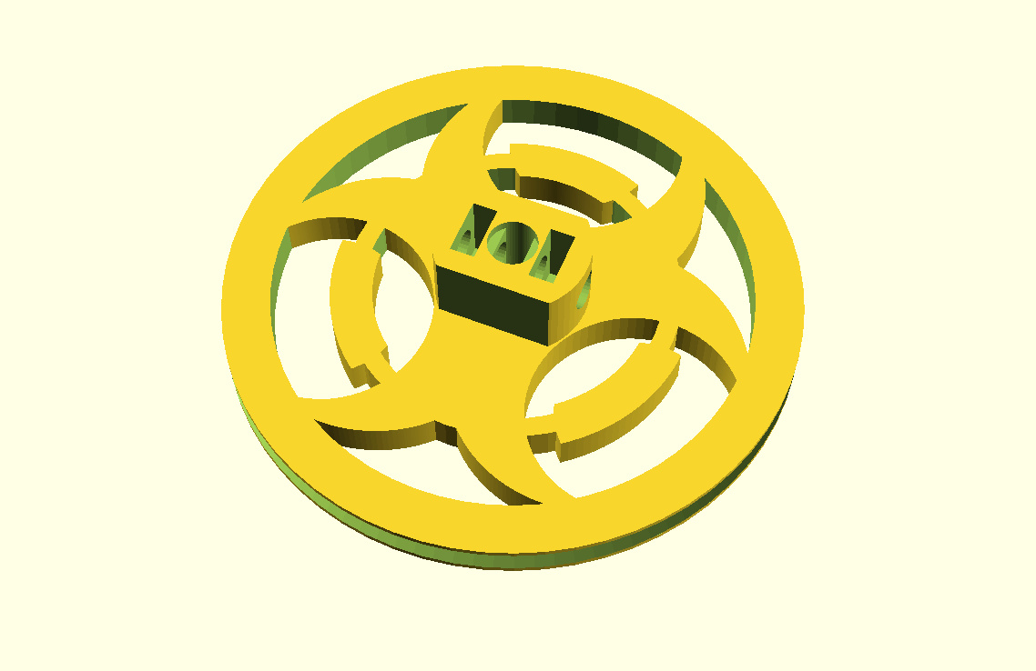
Print one each of the Chassis.stl, Caster.stl, PenCap.stl, Penholder.stl and two of the Wheel.stl files. When printed in their default orientation none of the parts should require supports when printed using a reasonably calibrated 3D printer. The layer height for the Chassis, Wheels and Caster are not critical. I’ve had good results printing with 0.30mm and 0.20mm layer heights on a Wanhao Duplicator i3 using Hatchbox PLA.
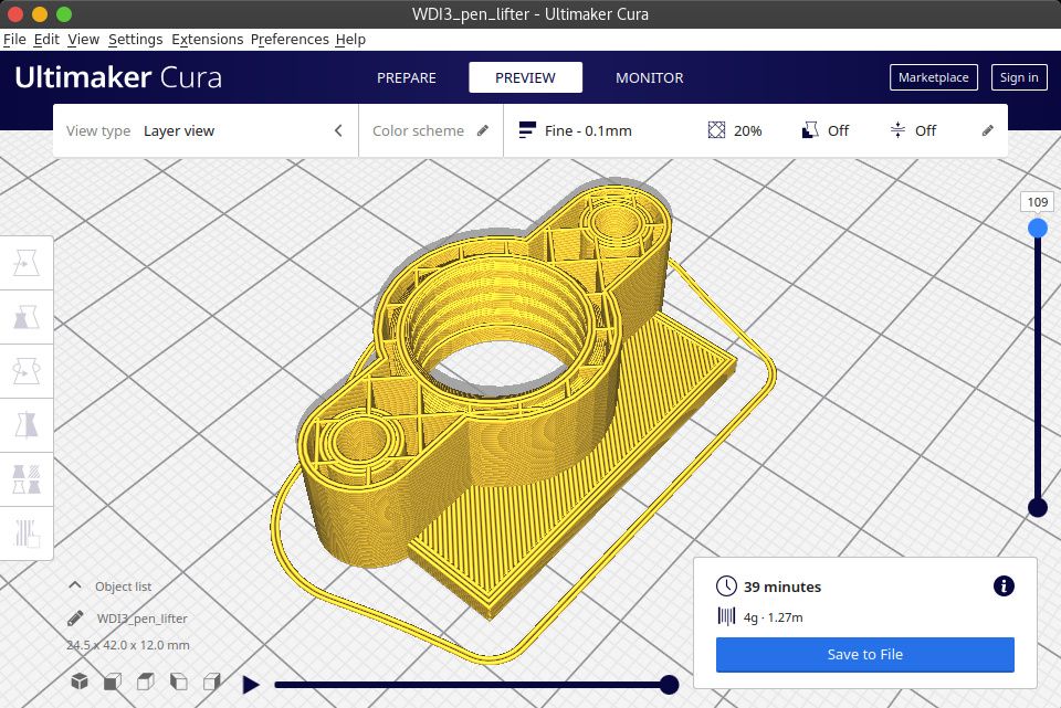
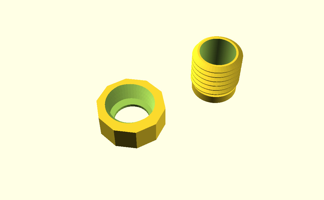
The Pen Lifter and Pen Holders should be printed with a 0.10mm layer height due to the threads in each part.
The pen_lifter has four captive 3x5x5mm Sleeve Bearing that are embedded during printing. When slicing the stl for printing find the layer number before the bearing pocket is covered and set the slicer to pause at this level then insert two Sleeve Bearings in each of the bearing pockets.
When printing with a 0.10mm layer height, this layer is 108 on my printer.

Attribution
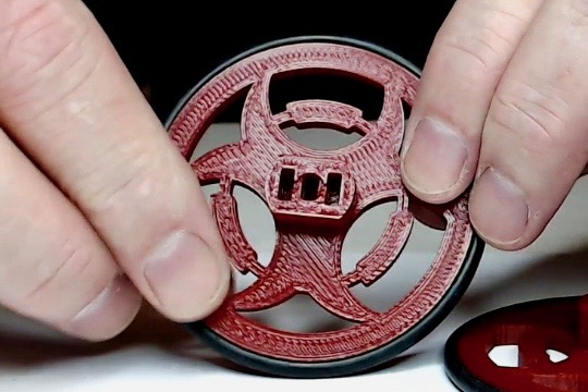
The shape of the wheel spokes were obtained from a Font Awesome icon under the Font Awesome Free License. It is available from https://fontawesome.com/icons/biohazard?style=solid
Quantity |
Part |
|
|---|---|---|
1 |
|
|
2 |
|
|
1 |
|
|
1 |
|
|
1 |
|
1.3. Assembly Instructions
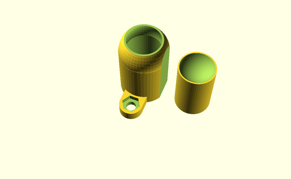
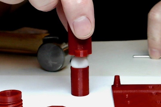
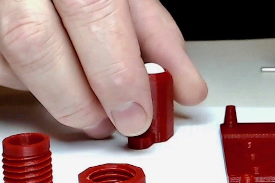
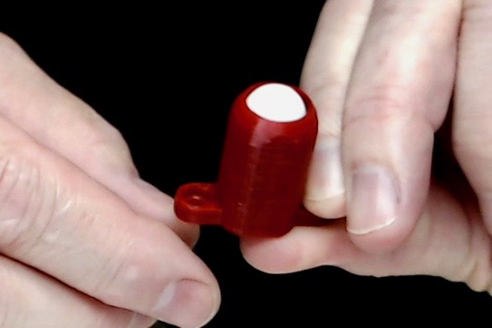
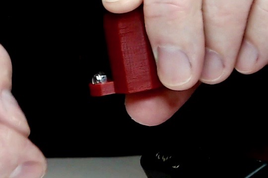
1.3.1. Step 1: Assemble the caster
Assemble the caster from the caster shell, 1/2” slingshot ball and caster plug by placing the slingshot ball on top of the plug then insert the plug into the caster shell.
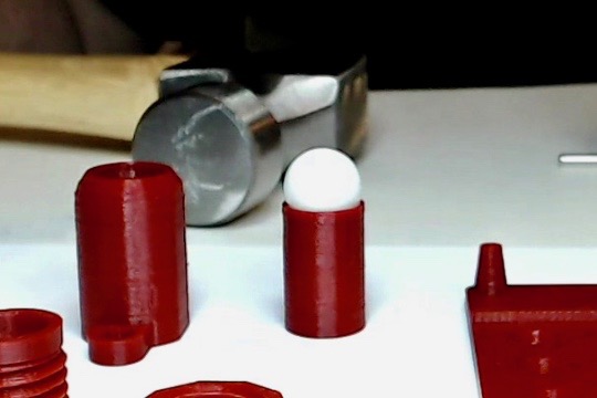
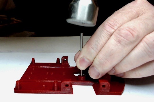
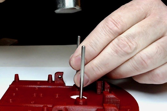
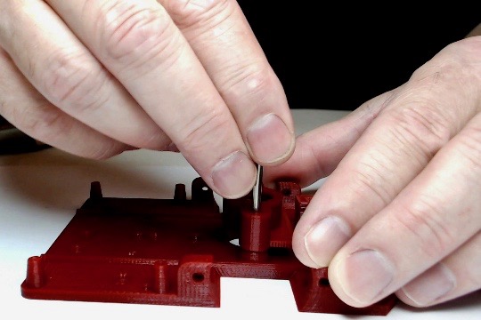
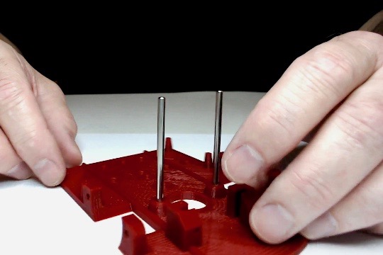
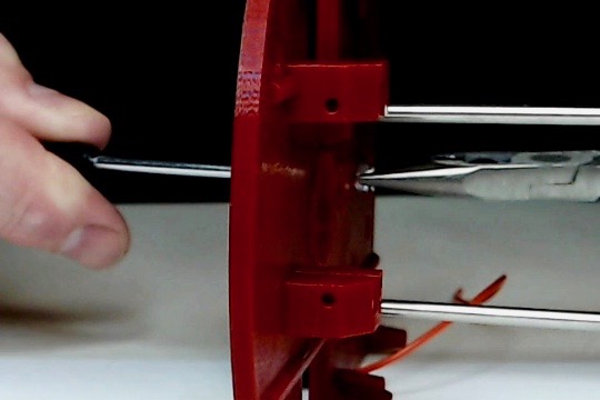
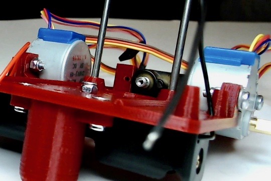
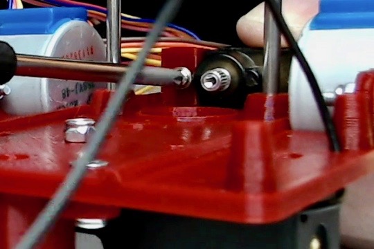
1.3.2. Step 2: Insert the pen lift dowels
Insert the two 3x50mm dowels into the two 3mm holes in the front of the chassis. The dowels are a tight press fit that may require the use of a hammer.
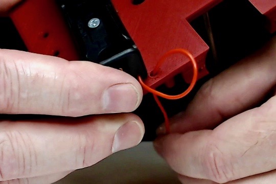
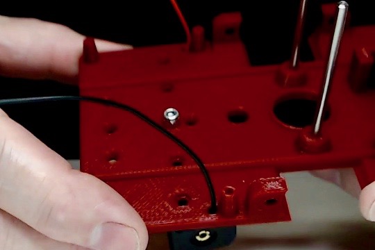
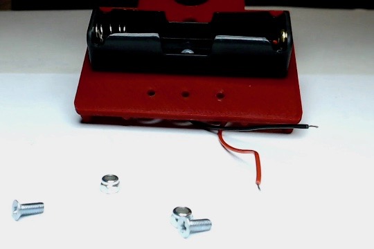
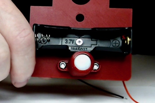
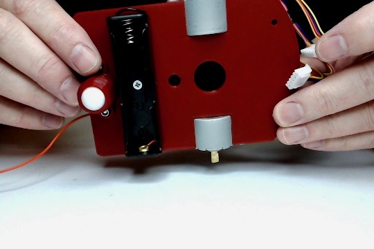
1.3.3. Step 3: Mount the 18650 battery holder
Use a M3x5mm flat head machine screw and M3 lock nut to mount the 18650 battery holder to the bottom of the chassis as shown.
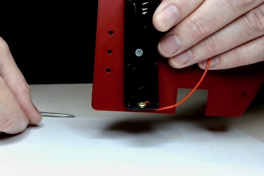
Run the battery holder wires through the holes in the bottom of the chassis as shown.
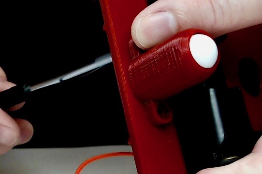
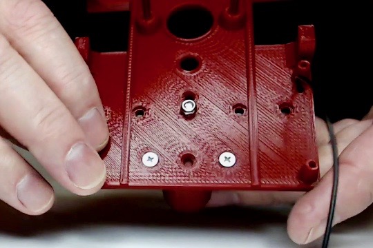
1.3.4. Step 4: Mount the caster
Use two M3x5mm flat head machine screws and M3 lock nuts to mount the caster to the bottom of the chassis as shown.
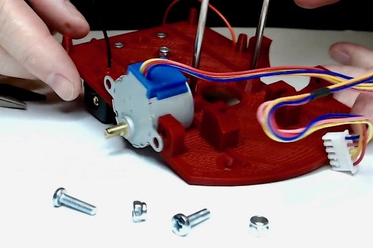
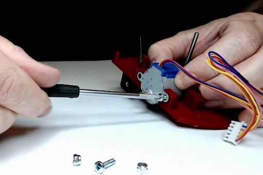
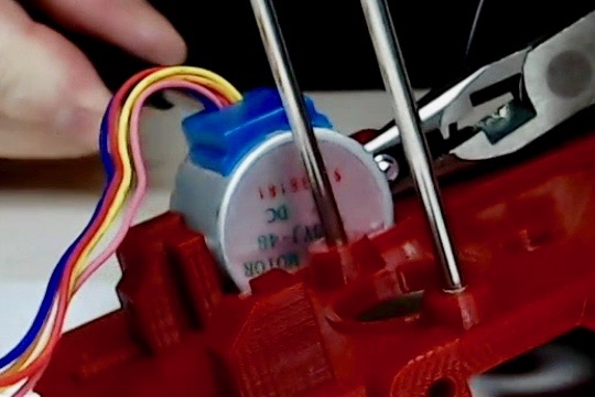
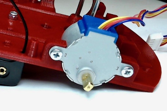
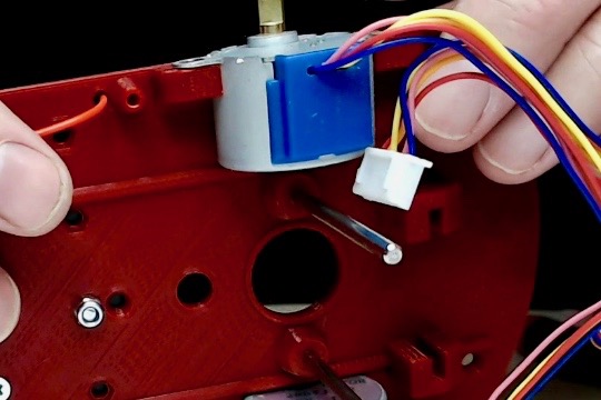
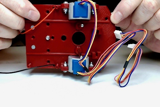
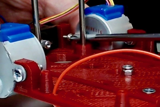
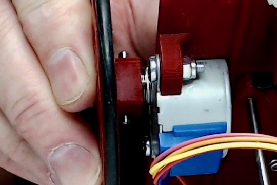
1.3.5. Step 5: Mount the stepper motors
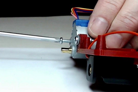
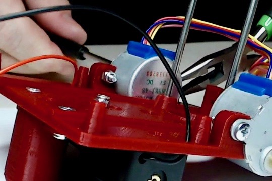
Use two M3x15 (or M3x12) machine screws and two M3 lock nuts to mount each of the 28byj-48 to the chassis as shown.
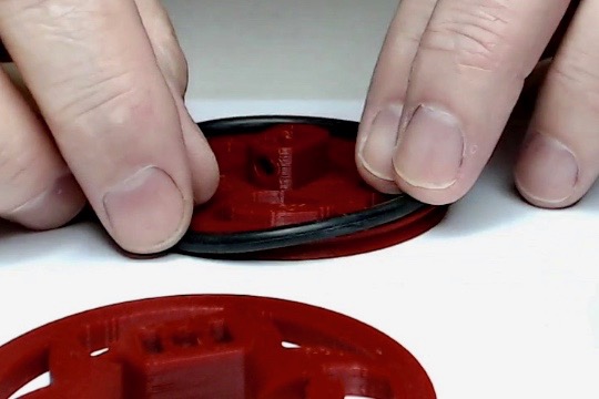
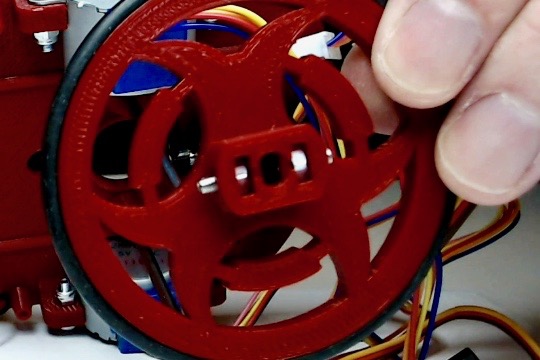
1.3.6. Step 6: Assemble the wheels
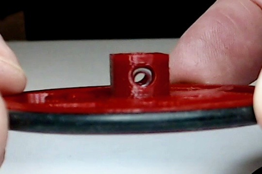
Fit an O-Ring around each of the wheels as shown.
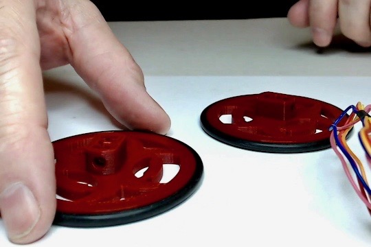
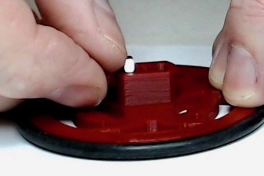
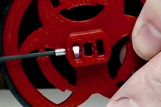
Insert two M3 hex nuts into the pockets in the wheel hubs as shown.
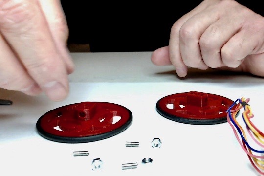
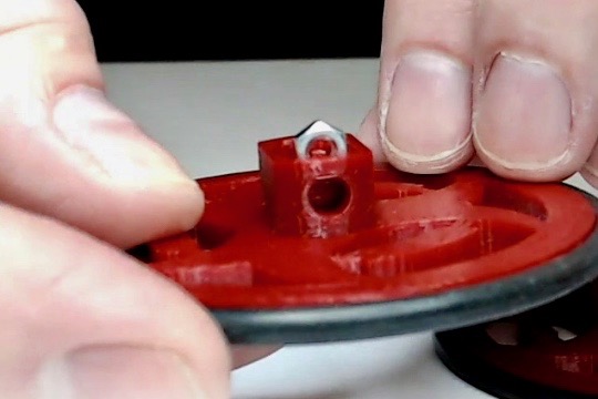
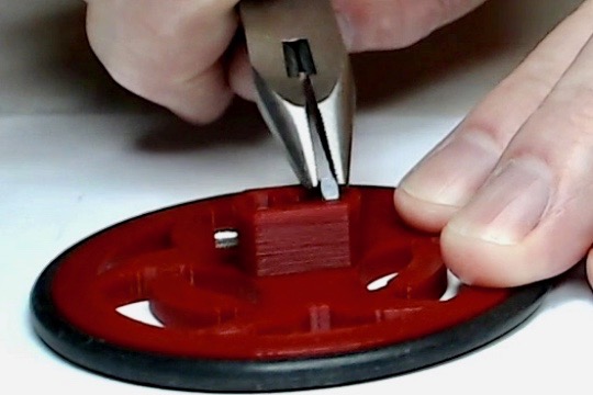
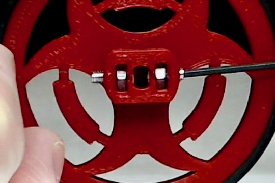
Inset two M3x10 machine screws into the M3 hex nuts in the wheel hubs a shown. The screws should not protrude into the motor shaft hole.
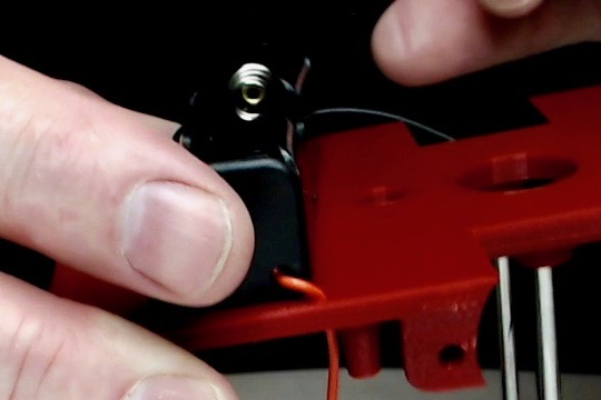
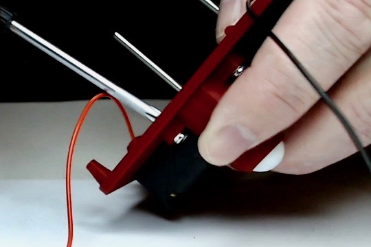
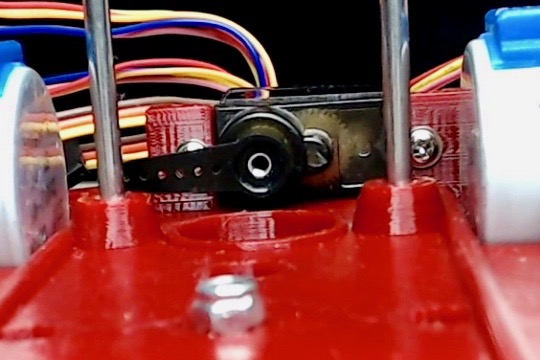
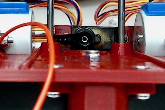
1.3.7. Step 7: Install the pen lift servo
Insert the MG90S servo into the slots in the front of the chassis as shown. The center of the servo’s shaft should be in the center of the pen hole in the chassis.
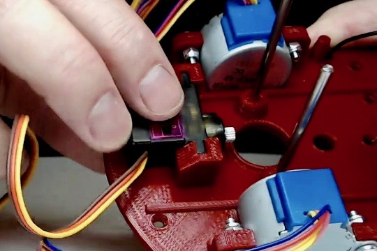
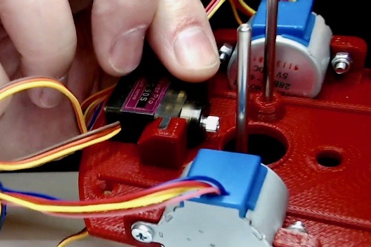
Use the two small self threading screws provided with the MG90S servo to hold the servo in place as shown.
Attach the small single sided servo horn onto the MG90S servo with the provided screw. The servo horn should be placed so it can move 180 degrees without hitting the chassis.
1.3.8. Step 8: Mount the wheels
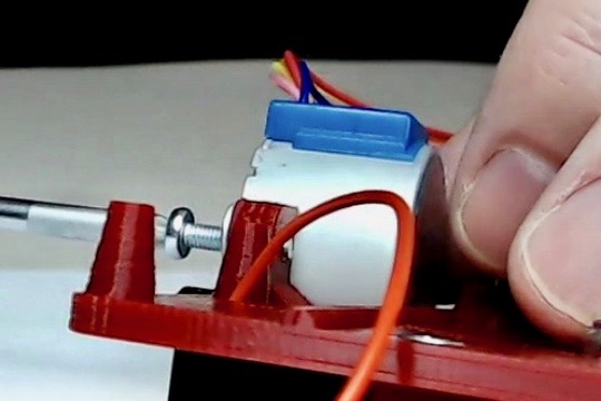
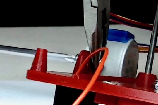
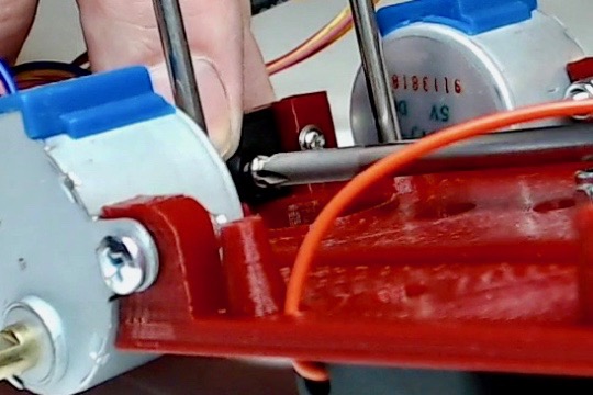
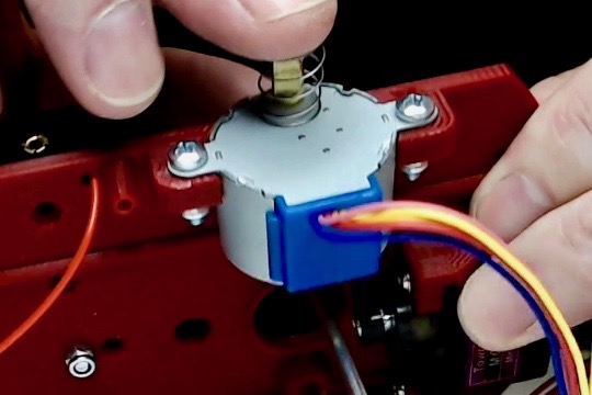
Place one of the 0.4x10x20mm steel springs over the stepper motor shaft as shown. The spring should fit around the flange surrounding the shaft.
Place the wheel onto the stepper motor shaft being careful to align the flat cutouts in the shaft with the cutouts in the wheel hub. The wheels are a press fit to the shaft that may require wiggling the wheel back and forth slightly to get them to slide all the way into the shaft. Lightly tighten the M3 screws on each side of the wheels to lock the wheel in place. You can use the screws to make small adjustments to the alignment of the wheels. Be careful not to overtighten the screw of you can crack the wheel hub.
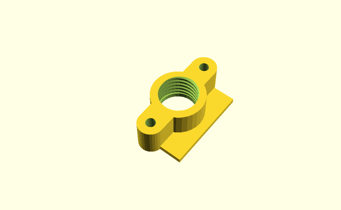
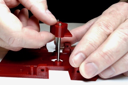
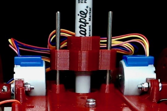
1.3.10. Step 10: Install the pen holder
Place the pen holder onto the chassis as shown. The pen holder should be centered over the pen hole in the chassis with the square pen lift flange facing forward over the pen lift servo’s horn.
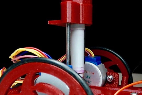
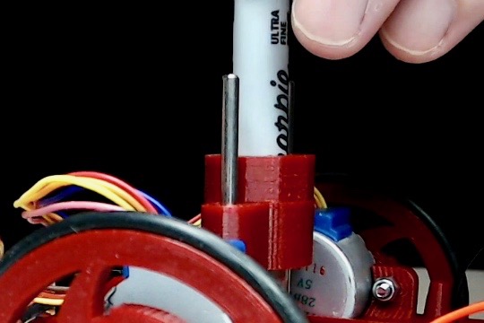
The pen holder should slide up and down the dowels freely. Initially there may be some resistance and it may not move easily enough to drop when raised and let go. A dab of light oil or PTFE lubricant will help. It should loosen up if you work the pen holder up and down the dowels for a little while. If it does not loosen up you should verify the dowels are parallel to each other. You can use light pressure to coax them into alignment.
1.3.11. Congratulations
Congratulations your TurtlePlotBot chassis is assembled. Continue onto to the next part, the Electronics Assembly.