3. Final Assembly Instructions
3.1. Power Requirements
The power requirements of the TurtlePlotBot vary considerably depending what it is doing at any given time. The ESP-32 Module will use around 20ma to 50ma with the LCD display and Wifi radio off. The LCD display will use about 20ma on average when turned on and will vary with the number of pixels that are lit. The Wifi interface will use around 130ma when idle and connected to an access point with frequent very short spikes of 600ma. The stepper motors will draw around 70ma for each coil that is active. When moving each motor will have two coil’s energized half of the time and one coil energized the other half. All of the coils are turned off after each move to save power. The MG90s servo used to raise and lower the drawing pen uses about 10ma when idle and 120ma to 250ma when moving and up 700ma if it is stalled or jammed.
3.1.1. 18650 Battery
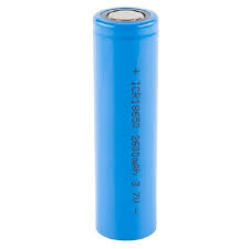
The TurtlePlotBot uses a rechargeable 18650 battery. These batteries come in low and high current versions. The high current version should be used since the charger used by the TurtlePlotBot charges at a rate of up to 2 amps. The wiring starting from pin 1 should be:
Pin |
Connector |
|---|---|
1 |
Battery Positive terminal |
2 |
Battery Negative terminal |
3 |
PC Jumper between pins 3&4 |
4 |
PC Jumper between pins 3&4 |
3.1.2. LiPo Cell
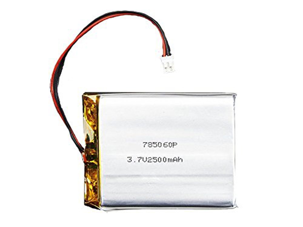
It is also possible to use a flat LiPo battery cell. There is no mount provided for this option but you can raise the ESP32 DrawBot board by using short standoffs between the board and the mounts on the TurtlePlotBot to create a space under the board to hold the LiPo battery cell. The wiring starting from pin 1 should be:
Pin |
Connector |
|---|---|
1 |
Battery Positive terminal |
2 |
Battery Negative terminal |
3 |
PC Jumper between pins 3&4 |
4 |
PC Jumper between pins 3&4 |
3.1.3. AA Batteries
Another option is to use four AA batteries. Alkaline AA batteries have the lowest up front cost but frequent use will drive up the cost quickly, using good quality rechargeable AA batteries are recommended. In an educational environment AA batteries maybe a more justifiable power source given their safety and ease of storage.
If you are using the AA battery option route the power wires from the batteries up over the chassis and between the pc board standoffs. The wiring starting from pin 1 should be:
Pin |
Connector |
|---|---|
1 |
Battery 1 Positive terminal |
2 |
Battery 1 Negative terminal |
3 |
Battery 2 Positive terminal |
4 |
Battery 2 Negative terminal |
3.1.4. Mount the DrawBot board
Mount the DrawBot Board to the chassis using four M2x5mm self tapping screws. Don’t overtighten the screws.
3.1.5. Connect the Stepper Motors
Insert the left stepper motor connector into the LEFT stepper socket on the DrawBot board and the right stepper motor connector into the RIGHT stepper socket on the DrawBot board. These connectors are keyed and polarized so they will only fit in the correct orientation. The blue wire should be closest to the front of the DrawBot board.
3.1.6. Connect the Pen Lift Servo
Connect the Pen Lift Servo to the PEN header. This header has 3 pins labeled ‘S’ for Signal, ‘5v” for 5 volt, and ‘G’ for ground. Most servos use Yellow or Orange wires for the Signal pin, Red for the 5 volt pin and Brown or Black for the Ground pin.
Carefully tuck the excess wire under the DrawBot board.
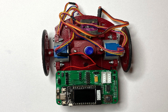
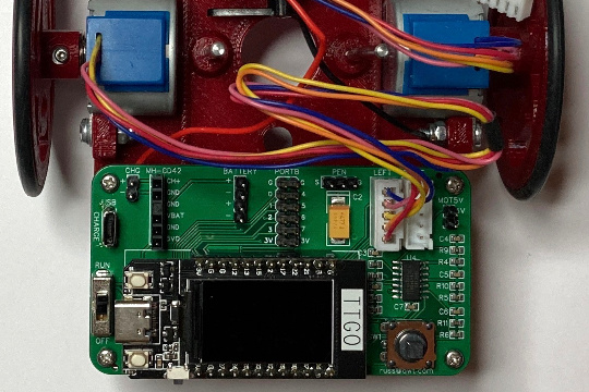
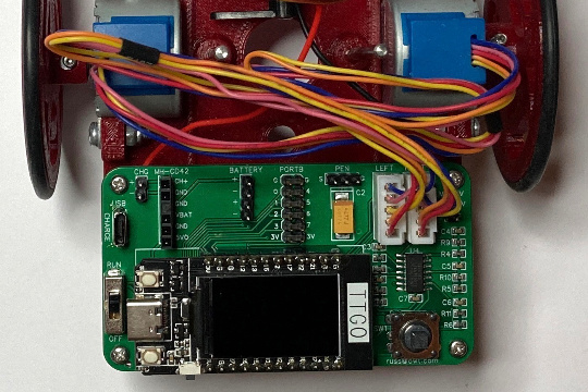
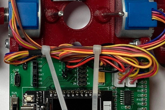
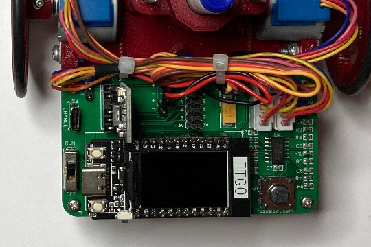
3.1.7. Dress the wires
Use a small cable tie to keep the wires in place and away from the Pen holder area.
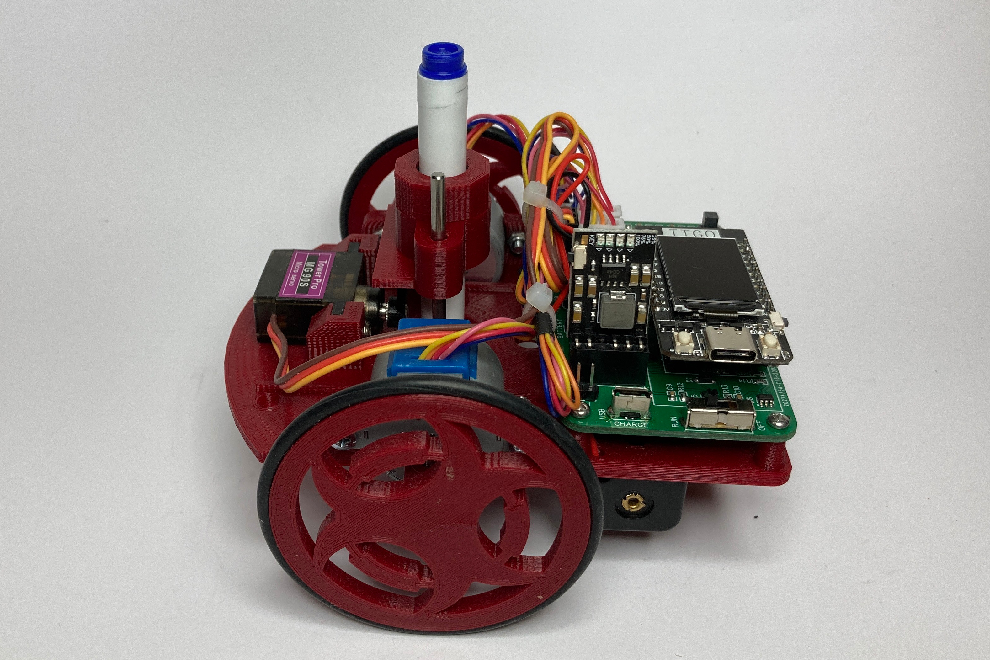
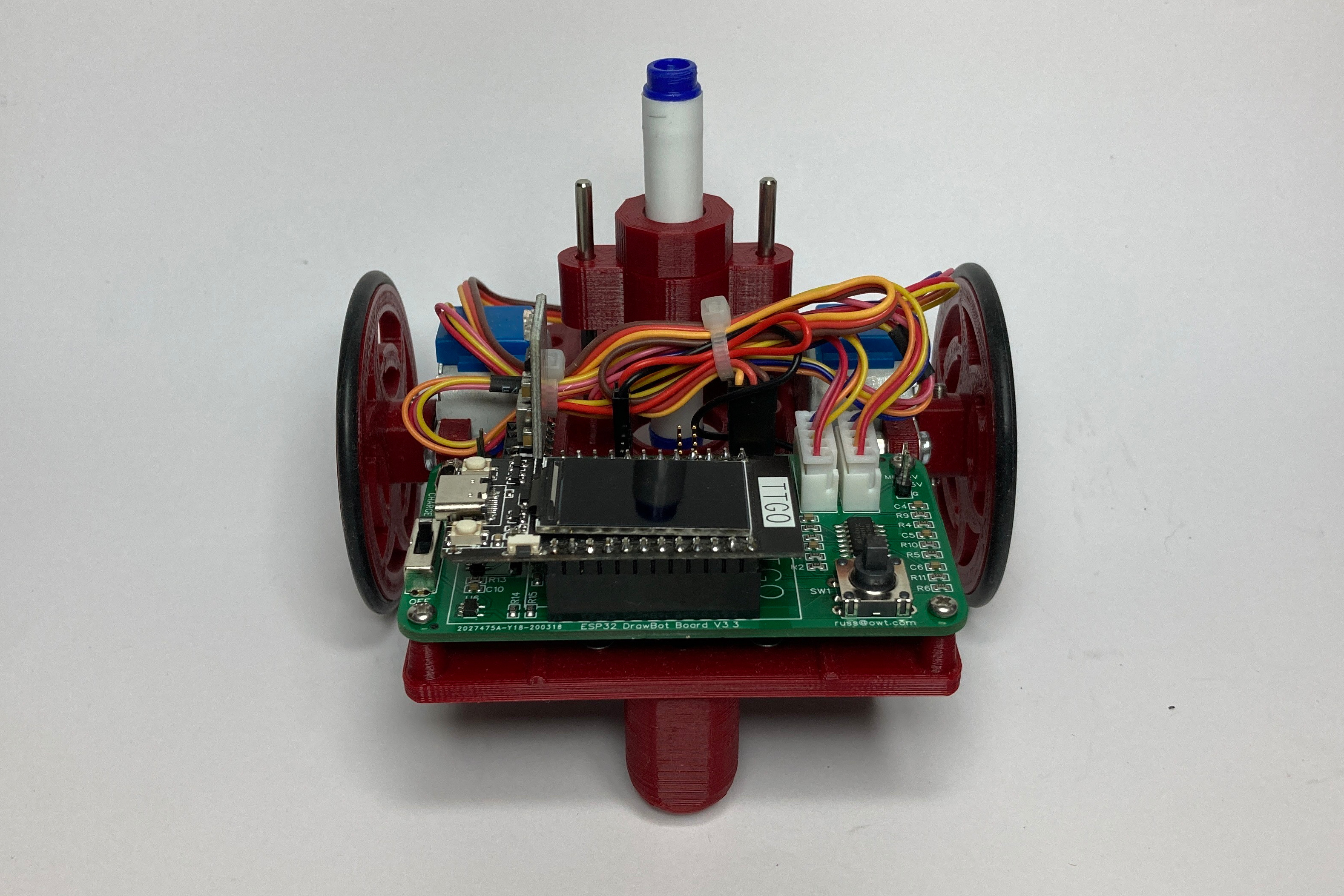
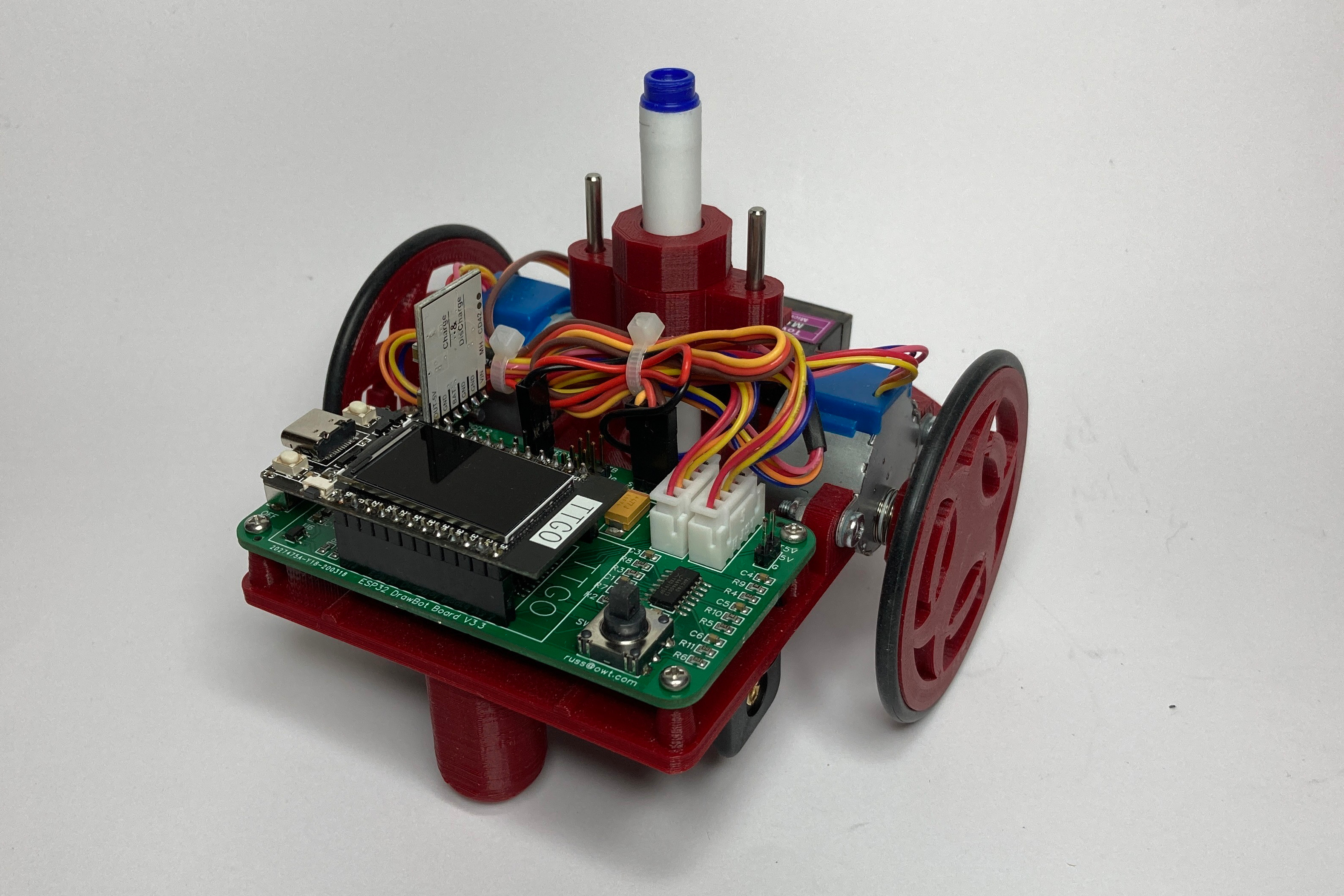
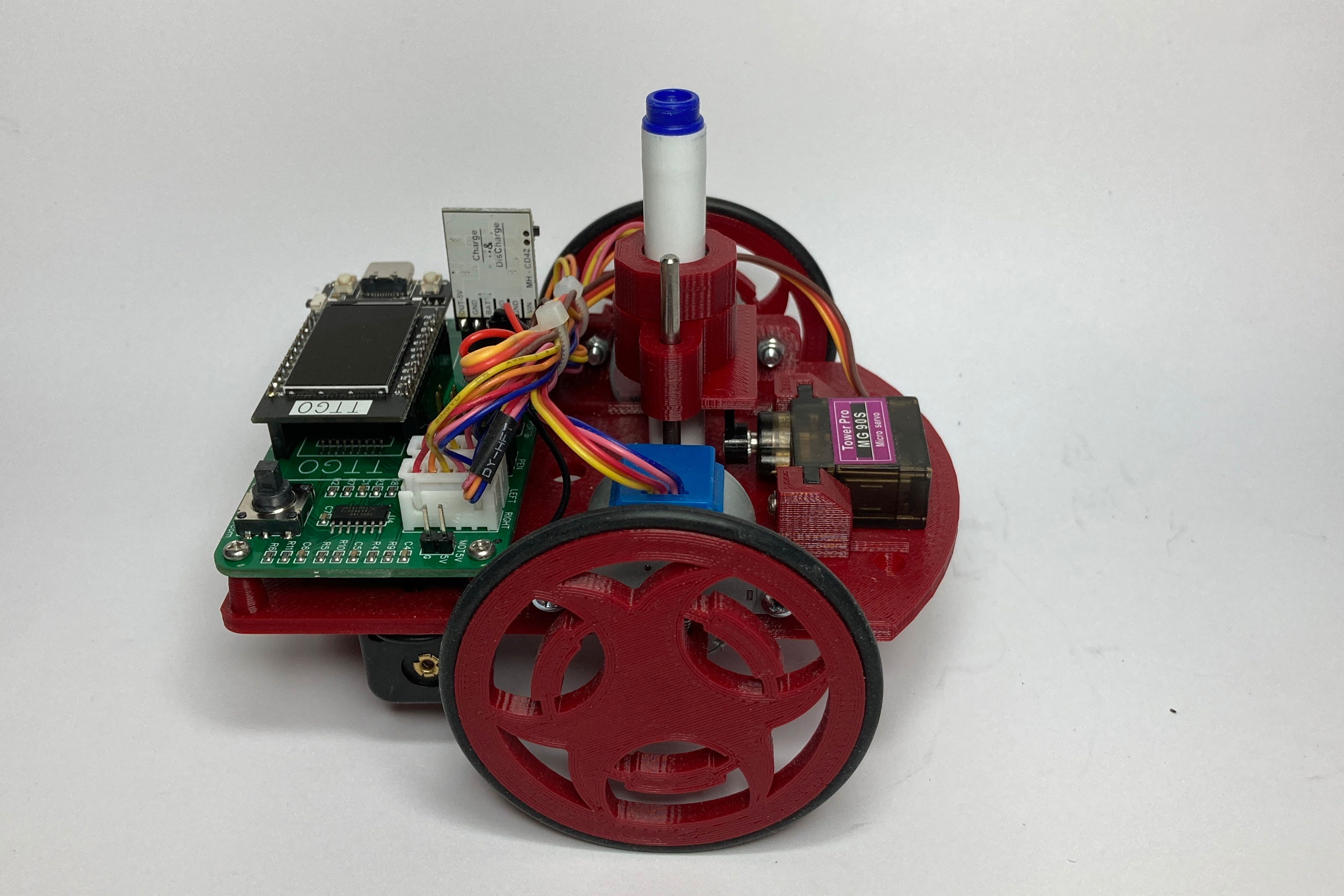
Here are some pictures of how I route the cables.
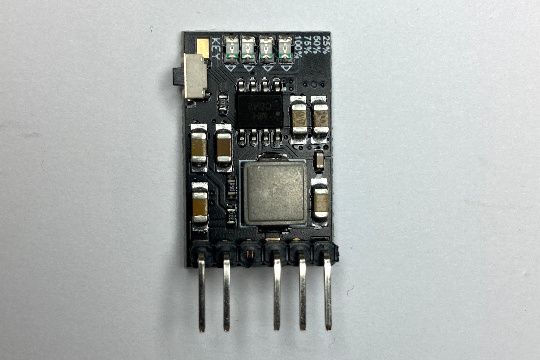
3.1.8. Charger/Boost module
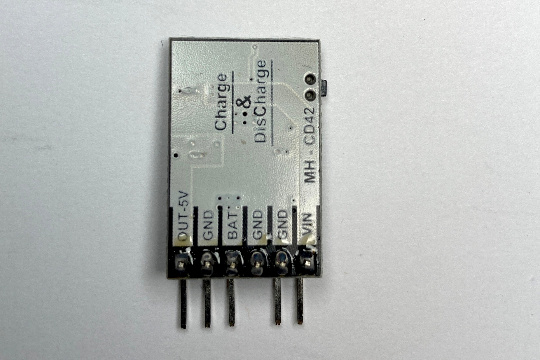
Solder a 6-pin 90 degree male header to the Charger/Boost module as shown. Remove Pin 3 by cutting it. The connector on the DrawBot Board has a connector keying plug in the hole for Pin 3. This is to prevent the Module from being plugged in backward.
3.1.9. Charger/Boost module Pinout
Pin |
Label |
Description |
1 |
VIN |
Charger Input Positive Terminal |
2 |
GND |
Ground |
3 |
GND |
Ground – Remove this pin |
4 |
BAT |
Battery Input Positive Terminal |
5 |
GND |
Ground |
6 |
OUT-5v |
5V Power Output |
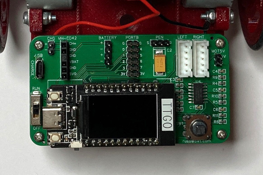
3.1.10. Install the Charger/Boost module
Insert the Charger/Boost module into MH-CD42 header as shown.
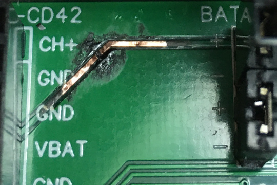
Warning
Plugging the module in backward will short the battery positive terminal to ground.
This is a fire hazard with powerful batteries and could damage the DrawBot Board.
Important
Do not use the charger on the Charger/Boost module with AA batteries even if they are rechargeable. The charge voltage is set for a single cell battery and the AA batteries have four cells wired in series
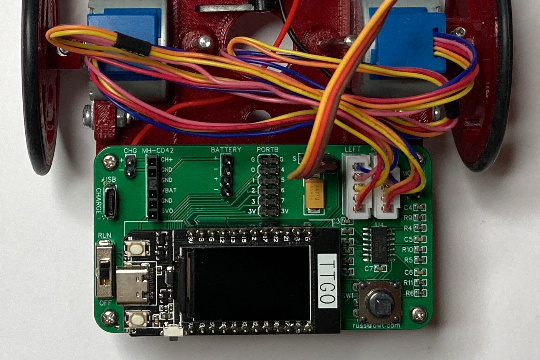
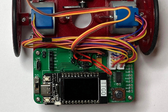
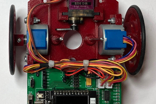
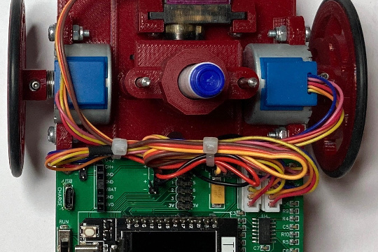
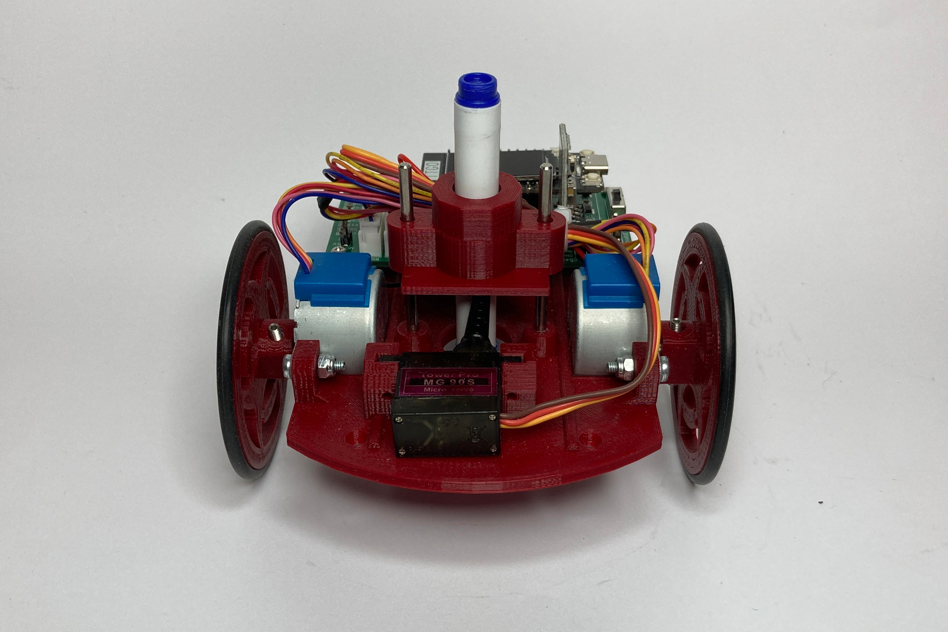
3.1.11. Congratulations
Your TurtlePlotBot is assembled and ready to be programmed. Here are a few more pictures of how your TurtlePlotBot should look. You can click on each image to view a Hires version.
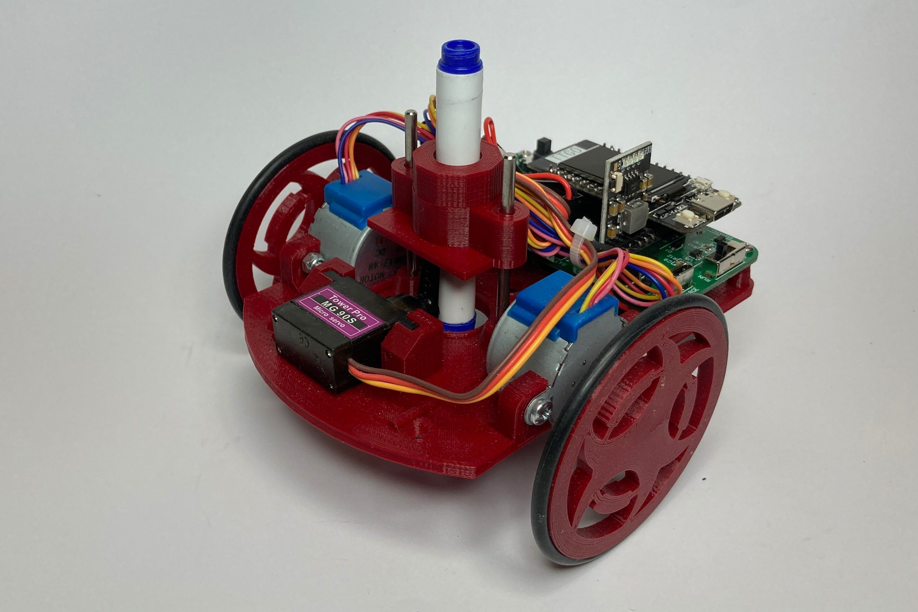


Continue onto to the next part, TurtlePlotBot Programming.