2. TurtlePlotBot Electronics


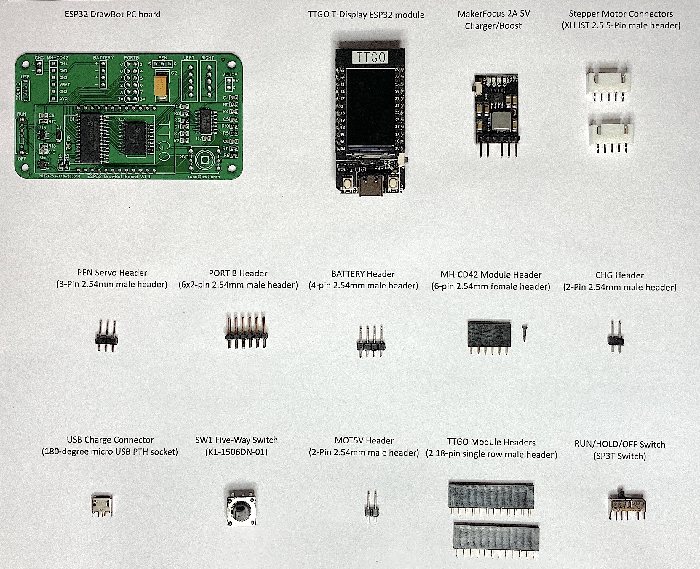
2.2. Parts List
Quantity |
Description |
|---|---|
1 |
ESP32 DrawBot PC board |
1 |
TTGO T-Display ESP32 module |
1 |
MakerFocus 2A 5V Charger/Boost |
1 |
180 degree micro USB pth socket |
1 |
K1-1506DN-01 5 way switch |
1 |
SP3T Switch |
2 |
18 pin single row male header |
1 |
6x2 pin male header |
1 |
6 pin female header |
1 |
4 pin male header |
1 |
3 Pin male header |
2 |
2 Pin male header |
2 |
XH JST 2.5 5 Pin male header |
1 |
18650 Battery or 4 AA Batteries |
2.3. Assembly Instructions
2.3.1. Stepper Motor Connectors
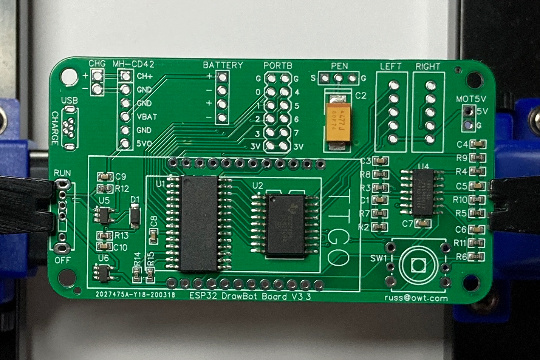
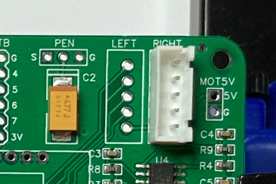
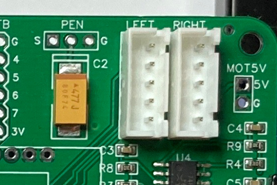
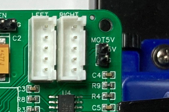
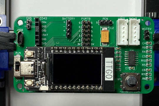
Place and solder the XH JST 2.5 5 Pin male headers in the areas labeled LEFT and RIGHT. These headers will provide power and control the left and right stepper motors.
I often use tape to hold components in place while soldering.
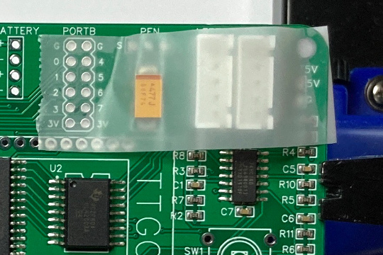
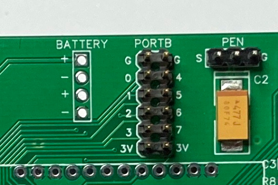
2.3.2. PEN Servo Header
Place and solder a three-pin male header in the area labeled PEN. This header will provide power and a signal to control the pen lift servo.
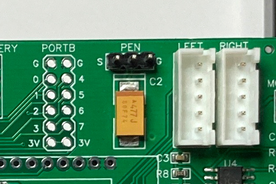
2.3.3. PORT B Header
Place and solder a 2x6 pin male header in the area labeled PORT B. This header provides power and 8 general purpose input/output pins.
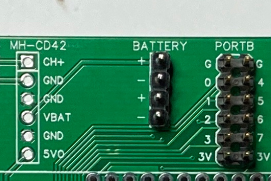
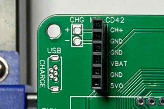
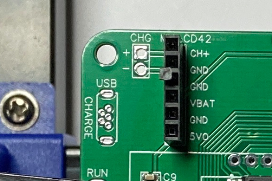
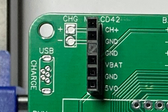
2.3.5. MH-CD42 Module Header
Place and solder a six-pin female header in the area labeled MH-CD42. Then insert a connector keying plug into the 3rd hole (GND) of the MH-CD42 header as shown. This prevents you from inserting the MH-CD42 modules backwards and shorting the battery.
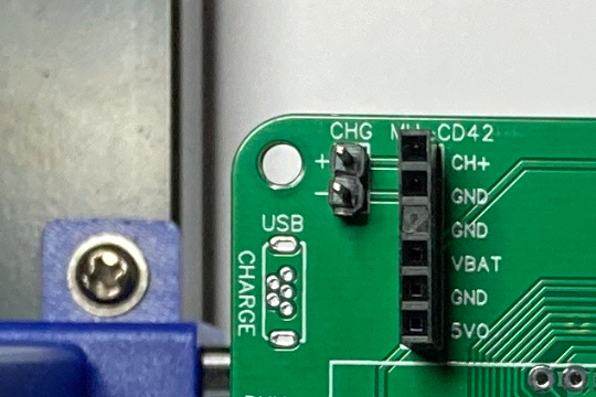
2.3.6. CHG Header
Place and solder a two-pin male header in the area labeled CHG. This header provides an alternative method to provide power to the charge circuit of the power module.
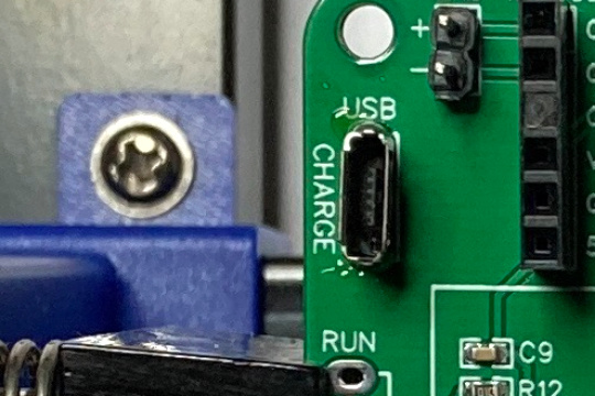
2.3.7. USB Charge Connector
Place and solder the 180 degree micro USB pth socket in the area labeled USB. This connector a charge only connection that is used to provide power to the charge circuit of the power module.
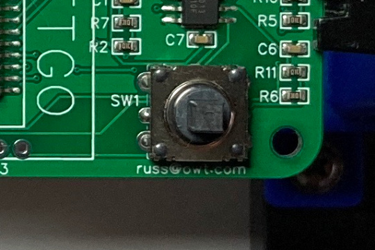
2.3.8. SW1 Five-Way Switch
Place and solder the K1-1506DN-01 5-way switch in the position labeled SW1.
2.3.9. MOT5V header
Place and solder a two-pin male header in the position labeled MOT5V. This header provides a connection to the 5V motor power.
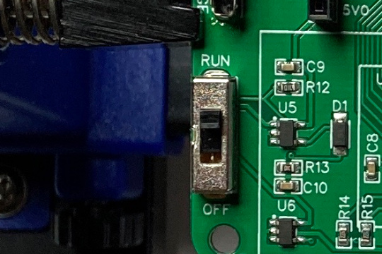
2.3.10. RUN/HOLD/OFF Switch
Place and solder the SP3T slide switch in the between the positions labeled RUN and OFF. This 3-position switch controls power to the processor and the motors. When the switch up in the RUN position power is provided to the processor and motors. When the switch is in the HOLD position power is provided only to the processor.
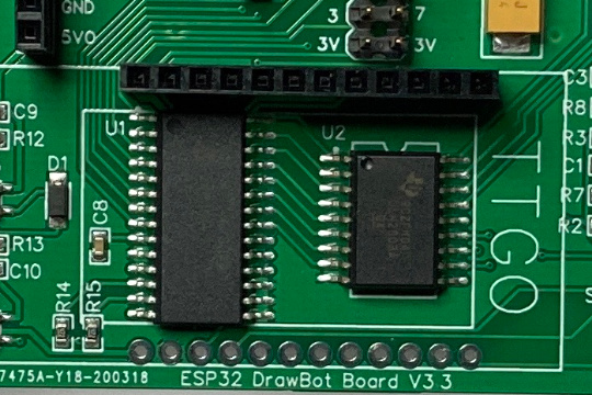
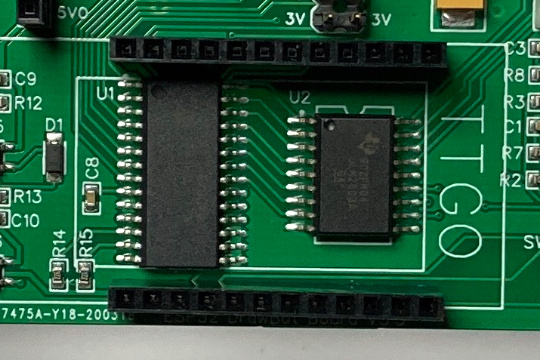
2.3.11. TTGO Module headers
Place and solder the two 18 pin single row male headers in the positions shown.
2.3.12. Congratulations
Congratulations your ESP32 DrawBot board is assembled.
Continue onto to the next part, the Final Assembly.